ROS 2 Autonomous Robot DIY Project #2:
Overview
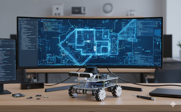
This project documents the development of a DIY autonomous vehicle using ESP32 micro-ROS.
Previous experiments included STM32-based balancing robots and Raspberry Pi car kits with Lidar.
Ultimately, the architecture transitioned to ROS2 Humble, with ESP32 handling IMU, Lidar, and odometry, while higher-level tasks ran on Raspberry Pi or a remote laptop.
Architecture
Architecture Overview
This diagram illustrates a high-level micro-ROS and ROS2 hybrid architecture for an autonomous vehicle. The system is designed to split workloads between a low-level microcontroller for hardware interfacing and a high-level computing unit for complex processing.
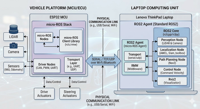
1. Vehicle Platform (ESP32 MCU)
The left side of the diagram represents the real-time hardware interface. The ESP32 acts as the bridge between the physical sensors/actuators and the main software stack.
micro-ROS Stack: It runs lightweight micro-ROS Nodes and a Client Library (rclc/rmw) specifically optimized for resource-constrained hardware.
Driver Nodes: These manage low-level communication protocols such as CAN, PWM, and UART.
Hardware I/O: It directly interfaces with various sensors (LiDAR, Camera, IMU, Odometry) and controls physical Drive and Steering Actuators.
2. Laptop Computing Unit (Standard ROS2)
The right side represents the central intelligence, typically running on a powerful laptop (e.g., Lenovo ThinkPad) using a full ROS2 installation.
ROS2 Agent (micro-ROS Agent): This is the critical middleware component that allows the micro-ROS nodes on the ESP32 to communicate seamlessly with the rest of the ROS2 ecosystem.
ROS2 Core & High-Level Nodes: This unit handles high-compute tasks that an MCU cannot perform:
Perception: Processing data from LiDAR and Cameras.
Localization: Determining position using AMCL or Slam_toolbox.
Path Planning: Navigating the environment using the Nav2 stack.
Control: Sending movement commands (Command Velocity).
Visualization: Monitoring the system state in real-time via Rviz2.
3. Communication Link
The two systems are bridged via a Physical Communication Link, ensuring data flow between the vehicle hardware and the computing unit.
Protocols: Data is exchanged using SERIAL, TCP, or UDP.
Physical Media: This can be established over USB/Serial, Wi-Fi, or Bluetooth, depending on whether the setup is tethered or wireless.
Hardware
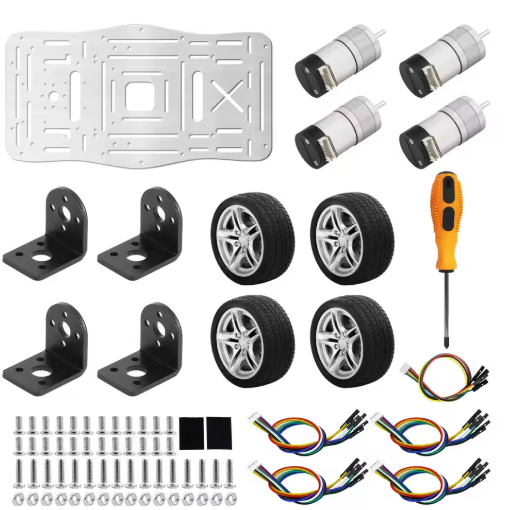
Chassis
- Accurate odometry requires a robust chassis.
- Encoder motors mounted on aluminum plates for durability.
- Selected Encoder Motor 310 for reliability.
- Initial camera gimbal was removed; future plan includes a depth camera.
- Current setup uses a 3D-printed Lidar mount.
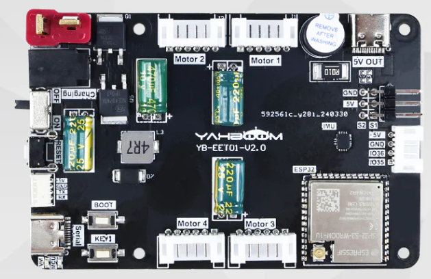
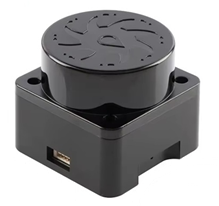
ESP32 micro-ROS Board
- Supports:
- 4 encoder motors
- 2 servos
- 1 custom serial port
- Integrated IMU
- Power: 7.4V T-type connector.
- Includes 5V, 4A USB-C port for Raspberry Pi.
- Mounting holes align with Raspberry Pi for stack integration.
T-mini Plus TOF Lidar
- No native micro-ROS driver available.
- Custom driver created in
idf.pybuild environment. - Firmware rebuilt using available source code.
- GitHub link to driver source provided in related blog entry.
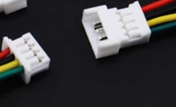
Cabling
- Lidar requires JST GH1.25 4-pin connector.
- ESP32 board uses JST Molex PicoBlade 4-pin.
- RX/TX crossover wiring required.
- Careful color matching for VCC, GND, RX, TX.
Encoder Motor Cabling
- Default cables too long; shortened using crimping tool.
- First-time use of PH2.0 JST sockets.
- Tool purchase requires attention, but PH2.0 is widely applicable.
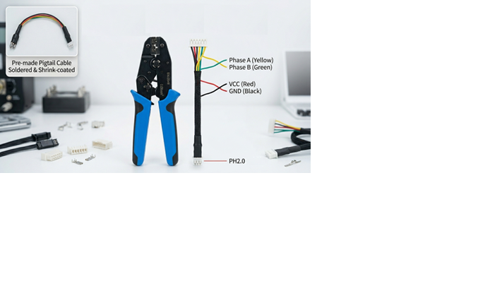
- For PH2.0,
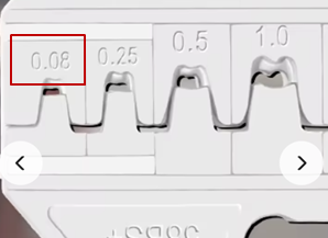 —
—
Software
- ROS2 Humble installed on Ubuntu acts as the micro-ROS agent.
- ESP32 firmware built with
idf.py menuconfig:- Wi-Fi configured.
- Agent IP set.
- Important note:
- ESP32 requires an antenna for Wi-Fi.
- Without antenna, deserialization errors occur.
- ROS2 command references available in earlier blog posts.
SLAM Mapping and Autonomous Driving
Process
- SLAM map creation requires slow, careful movement.
- Recommended tools:
teleop_twist_keyboard- Custom control applications
- Best practices:
- Use rotation (
j,lkeys) instead of reverse. - Cover reflective surfaces (e.g., windows).
- Ensure clear black wall outlines in the map.
- Use rotation (
Result
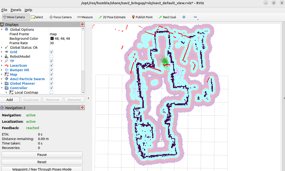
- Successfully generated SLAM map.
- Achieved basic autonomous driving in rviz2.
- Test confirmed feasibility of navigation.
Reflections
- Cable reliability was critical; avoided contact failures.
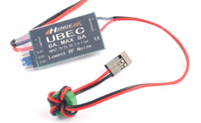
- Power stability ensured with UBEC.
- micro-ROS workload on ROS2 was significant due to multiple processes.
- Limitations:
- ESP32 supports only 1 Node, 3 Publishers, 3 Subscribers.
- TF and camera image processing handled on ROS2 agent instead.
- First-time CAD design and 3D printing for Lidar mount:
- Result was functional and effective.
- Project timeline:
- Preparation, execution, and testing took ~1 month.
- Delays mainly due to shipping; software prepared during waiting period.
Key Takeaways
- Attempting the build was essential—progress only comes through action.
- AI assistance played a crucial role in problem-solving and guidance.
- The project provided hands-on experience across hardware, software, and mechanics.